|
|
|
|
|
|
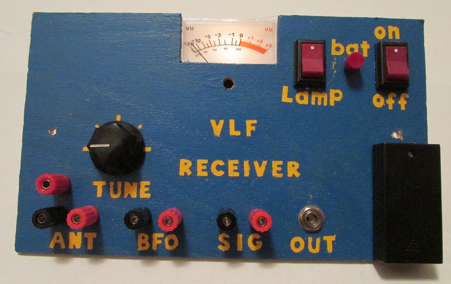
We used this VLF receiver to 'view' the big American solar eclipse of 2017. See at the bottom of the page the data we collected.
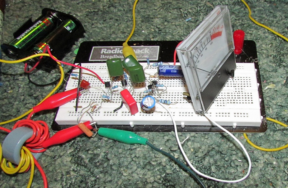
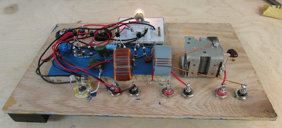
It works even when built like this on a solderless breadboard. This is how we built it at first for testing. We will move it to a permanent box with soldered connections. This page was updated on 06-02-2015.
Works with our SER22T line of antennas.
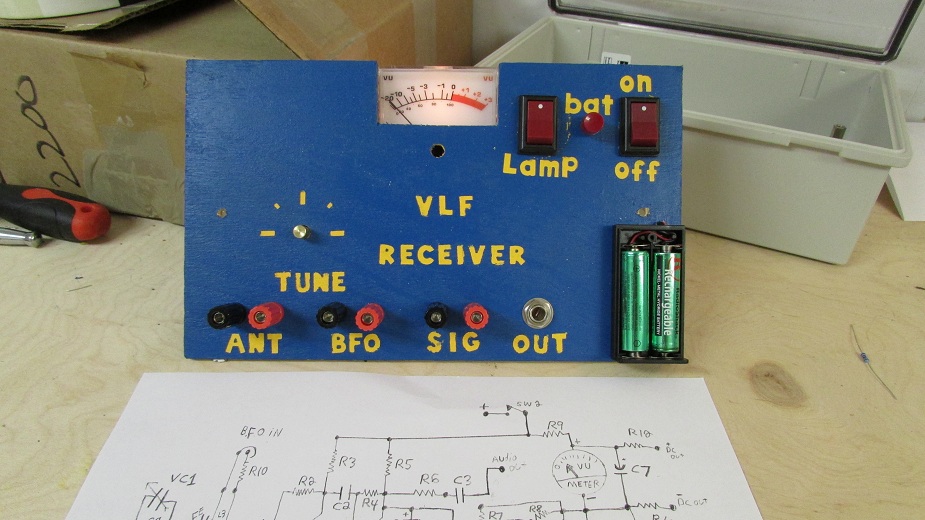
The intended application of this receiver is to monitor signal strength of time code station WWVB at 60 KHz.
The receiver has a signal strength DC output available to allow recording of received signal strength to a chart recorder app.
The signal from WWVB fades or is weaker during the daytime due to solar atmospheric ionisation. At night this effect dissipates and WWVB comes up to full signal strength.
Monitoring WWVB's signal strength can allow detection of solar flares, x-ray bursts, gamma ray bursts, or other space events that greatly disturb the ionosphere, causing a sudden drop or increase in signal strength.
You can also watch WWVB fade out an hour before local sunrise, and signal level increases at night an hour after sunset each day. A sudden drop in recorded signal strength at night indicates you may have recoreded an astronomical event.
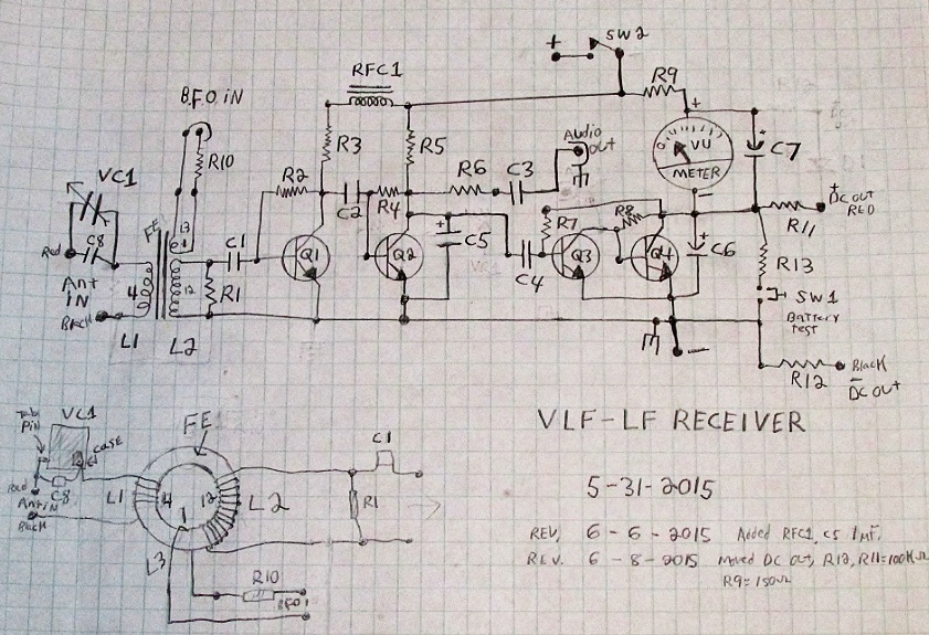
This receiver is a work in progress. More will be added as work progresses. Date: 06-02-2015.
Parts list:
Tuned Antenna required: Any Stormwise SER22T antenna for use in bands between between 10 KHz to 300 KHz.
FE = Stormwise VLF-LF Transformer Core # 1 $ 7.00 each + s/h.
L1 = 4 turns # 22 copper magnet wire wound on FE. See diagram and photos.
NOTE L1: Selectivity is the ability of the receiver to separate stations on the dial. 4 turns gives good selectivity. 3 turns gives even more selectivity. 2 turns gives narrow selectivity. 5 turns gives less selectivity.
NOTE: In our receiver we changed L1 to 2 turns on 06-26-2015, giving much better selectivity performance.
L2 = 12 turns # 22 copper magnet wire wound on FE. See diagram and photos.
Note L2: 12 turns works well from 10 KHz - 300 KHz with FE part.
L3 = 1 turn # 22 wire wound on FE. See diagram and photos.
NOTE: L3: 1 turn is -ALL- that is needed to effectively couple the BFO signal into the FE core. Don't overdrive it, you'll loose headroom on signal strength measurements, but feel free to experiment, depending on your needs.
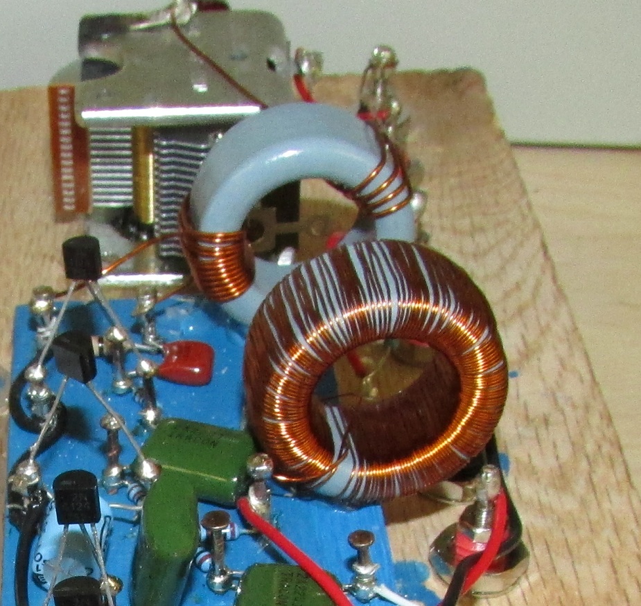
RFC1 = 144 turns # 28 wire wound on separate FE core. See photos.
NOTE: Do not omit RFC1, it provides the needed signal blocking to force the received signals into the Q2 audio detector stage. Wire in as shown in the diagram and photos.
VC1 = 15 pF - 384 pF variable capacitor. Stormwise part # AMVC-384 $ 20.00 each + s/h.
Q1, Q2, Q3, Q4 = 2N4124, or 2N3904 NPN small signal transistors.
We used 2N4142 NPN transistors in our receiver.
C1 = 0.047 uF.
C2 = 0.22 uF.
C3 = 0.22 uF.
C4 = 0.22 uF.
C5 = 1 uF.
C6 = 220 uF.
C7 = 470 uF. Omit this part if quick meter response is desired.
C8 = 500 pF mica capacitor or other high Q type low loss capacitor.
R1 = 10 K-ohms
R2 = 47 K-ohms
R3 = 2 K-ohms.
R4 = 47 K-ohms.
R5 = 2 K-ohms.
R6 = 2 K-ohms.
R7 = 470 K-ohms.
R8 = 33 K-ohms. NOTE: You may want to use a 50 K trimmer resistor for precise adjustment of the signal meter. The correct adjustment is the following for highest signal sensitivity: The meter should just barely indicate (it should move about the width of meter's pointer) above 0 when power is turned ON with nothing connected to the receiver. Be sure to use fresh or fully charged batteries during this calibration. Correct adjustment will give you the highest sensitivity of your signal meter, regardless of what type of analog meter you are using. However, if you want less meter sensitivity on your receiver you can adjust R8 to match your exact requirement. Some VLF signals increase greatly at night so you may need to adjust your meter level to match your research needs based on this fact.
R9 = 50 ohms to 200 ohms. We used 100 ohms. Exact value depends on your meter's sensitivity. Adjust this value so meter will not slam off scale on strongest signals. Adjust it to meet your research needs. Make sure that the strongest signals will give a slightly past full scale reading for best performance. Use fresh batteries or newly recharged batteries for the calibration. We will be using rechargeable batteries so these have a slightly less voltage than standard AA batteries, so we did all testing with them.
R10 = 47 K-ohms. This resistor keeps the BFO drive level to a low managable value, and increases dynamic range when operating in BFO mode. BFO drive levels of 0.1 volt to 1.5 volt are input to the BFO jack. Helps to prevent overdriving the core.
R11 = 100 K-ohms. High resistor value allows DC thru but blocks any RFI that might come from connected recording equipment.
R12 = 100 K-ohms. High resistor value allows DC thru but blocks any RFI that might come from connected recording equipment.
R13 = approximately 500 ohms, for battery test meter function, but exact value will be based on your meter.
SW1 = momentary pushbutton switch for battery test function. Set meter reading to 100 percent with new fresh batteries at a total of 3 volts, if only for calibration. NiMH batteries will read lower on the meter by 0.5 volt.
NOTE: SW1: use this switch for output level calibration when recording to a chart recorder. Press to help set the high level value.
SW2 = ON / OFF switch. Power switch.
SW3 = ON / OFF switch. Meter back light switch. (not shown in diagram).
METER: Mouser part number [ ] or any meter having a 120 ohm to 200 ohm coil movement. Meter shown has a 120 ohm coil movement. You can use the meter movement from an analog volt meter also, it does not have to be the same one shown here. If the meter has a coil resistance greater than 200 ohms, place a resistor across the meter terminals to make the total resistance 200 ohms. The receiver's signal meter circuit is looking for a meter load of about 200 ohms total. R9 makes up for the difference if the meter is lower value than 200 ohms.
Important note: Some VU meter's come supplied with an external diode bridge that can be connected to the meter to allow readings of audio levels. Do NOT use this part in the signal meter circuit. Make sure your selected meter does NOT have a built in diode bridge.
Panel Meters of all kinds can be found at this link
Lamp: 6 volt hobby filament lamp. Hillman brand part number 881510, [SKU# 0823671901] from Lowes Hardware Stores. Great for back-lighting the meter at 3 volts DC.
AA-cell Plastic Battery Holder: Hillman brand from Lowes Hardware Stores. Hillman brand part number 884473. Holds two "AA" batteries.
This receiver is designed to work work on 2 AA cell batteries of 1.5 volt each for a total of 3 volts. It will operate down to 1.5 volt so it works great with rechargable NiMH batteries which are typically 1.25 volt each for a total of 2.5 volts.
The receiver will also work on just one 1.5 volt battery, however the signal meter function requires that the battery voltage be above 2 volts.
Connect an audio amplifier having a 5000 ohm microphone input impedance at 1 mV sensitivity, for very loud reception. The receiver will also drive line-level jack of an audio amplifier.
You can also use a pair of mono headphones or an earphone directly from the receiver's output jack, though not too loud, the WWVB signal is hearable in headphones with no extra amplification.
From any sinewave signal generator, feed in a sine wave of 0.3 volts rms to the BFO input at 59.60 KHz. This will produce a beat note of 400 Hz from the speaker when WWVB is tuned in. The signal meter should swing past full scale when WWVB is coming in strong at night. Reduce BFO input drive to about 0.1 volt input or until meter reads 75 percent of scale when doing scientific research (leaves some headroom for signals to increase further). Use the BFO drive input level like an RF gain or volume control.
NOTE: The receiver is designed for the BFO frequency to be LOWER in frequency than the received signal at 60 KHz. A BFO input of 60.4 KHz will also produce a beat note of 400 Hz, but it is much weaker than when a frequency of 59.50 KHz is used as the BFO input.
The receiver has a peak audio detector response between 150 Hz to 500 Hz, with the center being around 300 Hz. This value is set by C5 value of 1 uF. C5 also prevents the BFO drive from entering the signal strength meter and causing meter to indicate a signal, when no input signal is present.
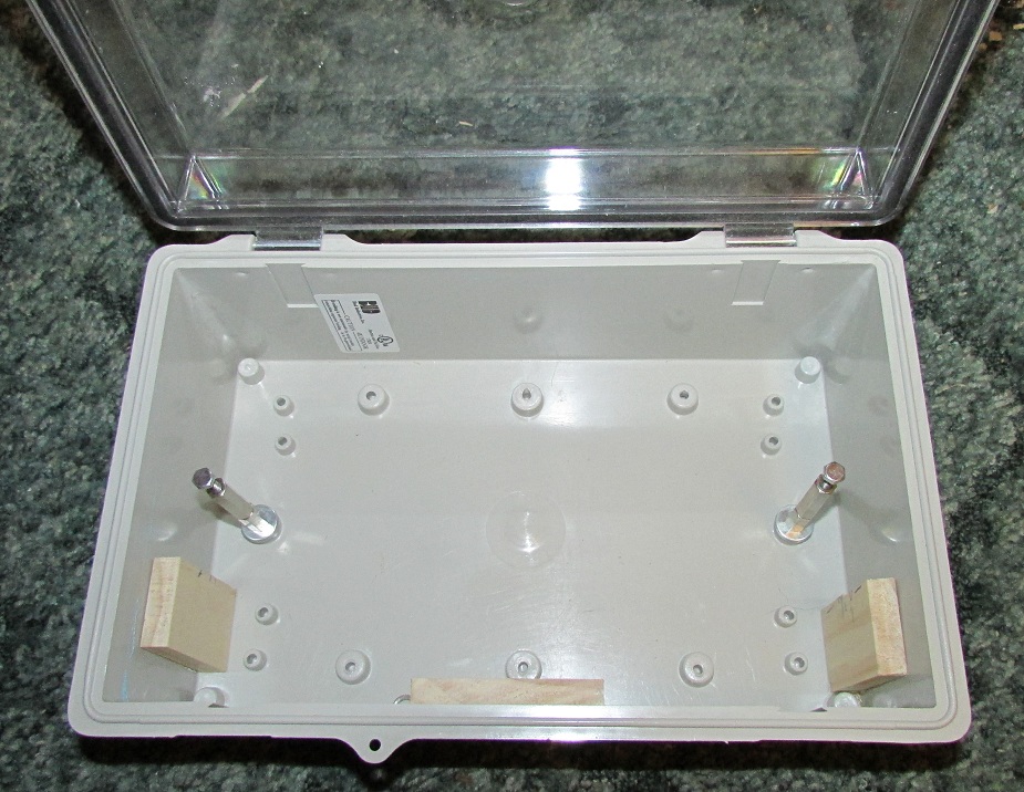
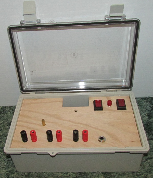
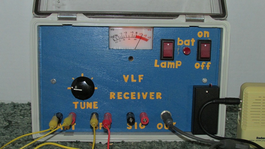
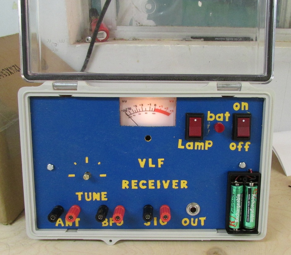
A 'pelican' brand plastic case is being used for the receiver project. Other cases may be used also.
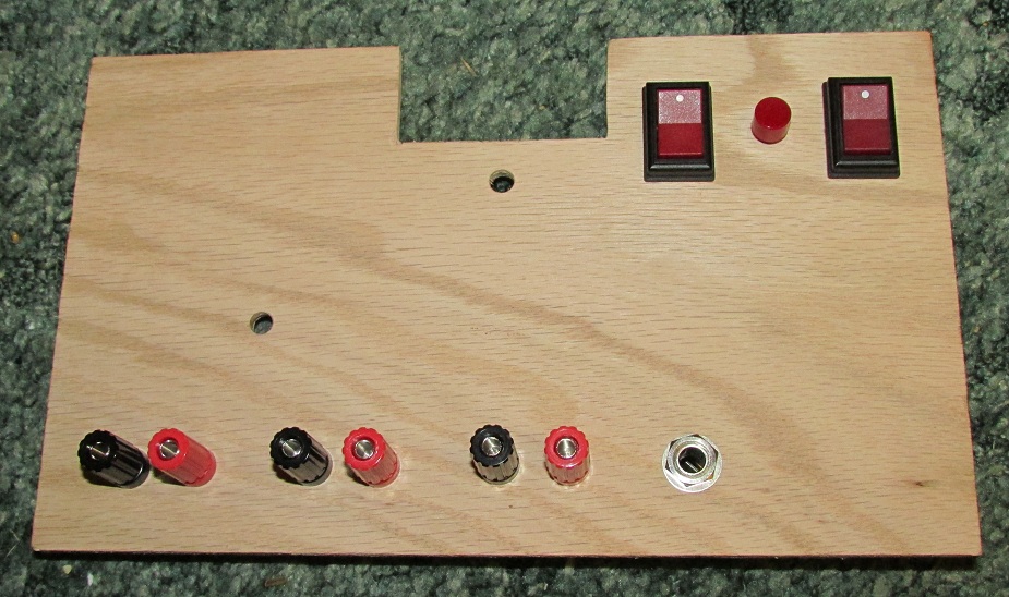
The wood front panel piece is made of oak wood and is 9 and 15/16ths inches wide and 5 and 15/16ths inches high and 0.2 inch thick. In this photo the wood has not yet been painted and stenciled with the lettering. Remove the parts before painting or staining.
The receiver will have ON / OFF, battery test, and meter light switch.
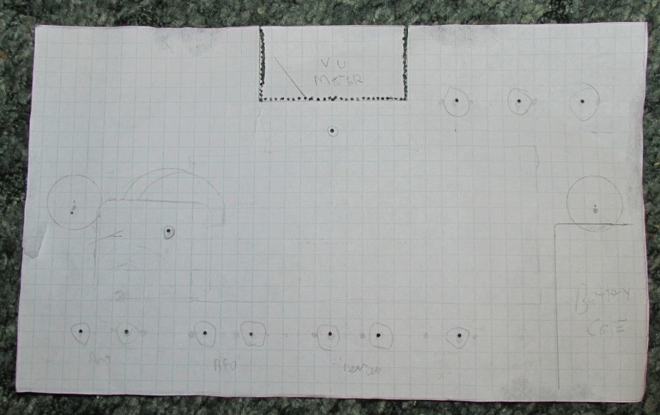
A drawing template was made on a piece of graph paper. The size is 1:1 and it was taped onto the wood board and was drilled thru the marked points. The cut out of the meter hole was done by drilling out the part of the board along where the meter will be mounted. Use as small a drill bit as you can find, and drill holes carefully along the inside of the lines you mark. The use a hack saw to gently cut down the vertical portions. The whole piece can be snapped out, then use sand paper to smooth down the drill holes. You can also use a jig saw to cut out the whole piece without needing to drill the 100 tiny holes along the lines.
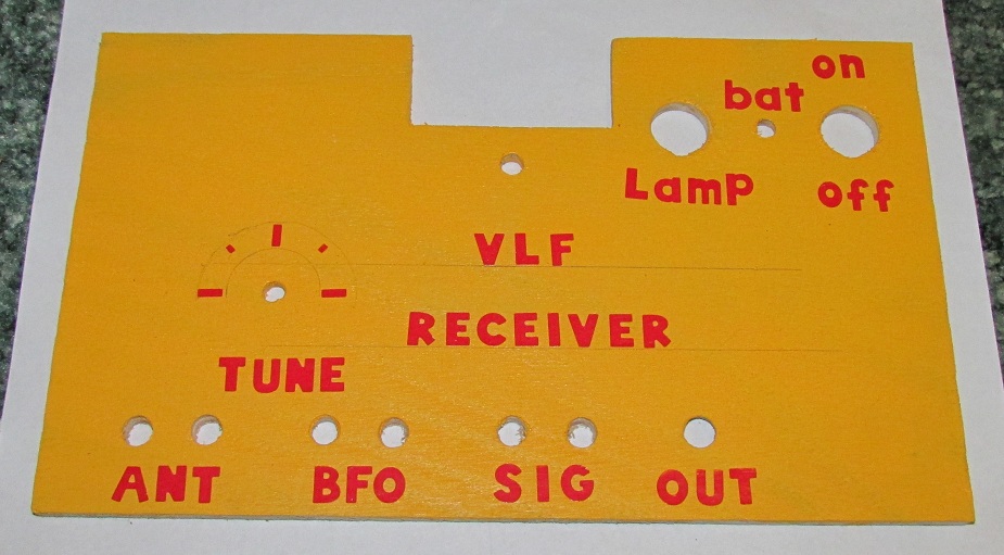
6-3-2015. The wood panel was painted with house paint from Lowes. A color called 'orange ice' was mixed as a half-pint sample for a few dollars.
When the paint was dry, red sticky-back lettering was placed to mask off the area that will be painted over. The wood panel will next be painted over with a dark blue color. Then after the blue paint is dry the red lettering will be removed to reveal the 'orange ice' colored lettering.
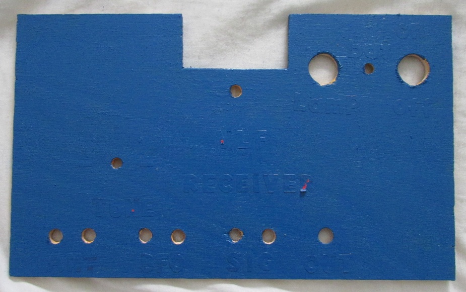
06-05-2015, The front panel was painted with blue paint over the stickyback letters and the orange ice color paint.
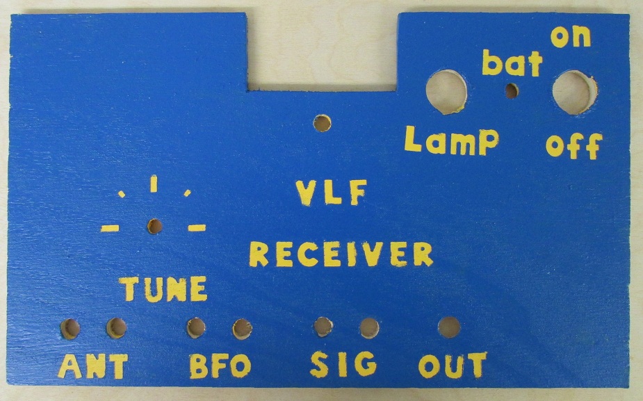
06-05-2015, The paper letters were peeled up showing the orange ice color paint below, to make the lettering a permanent on the front panel.
ASSEMBLY:
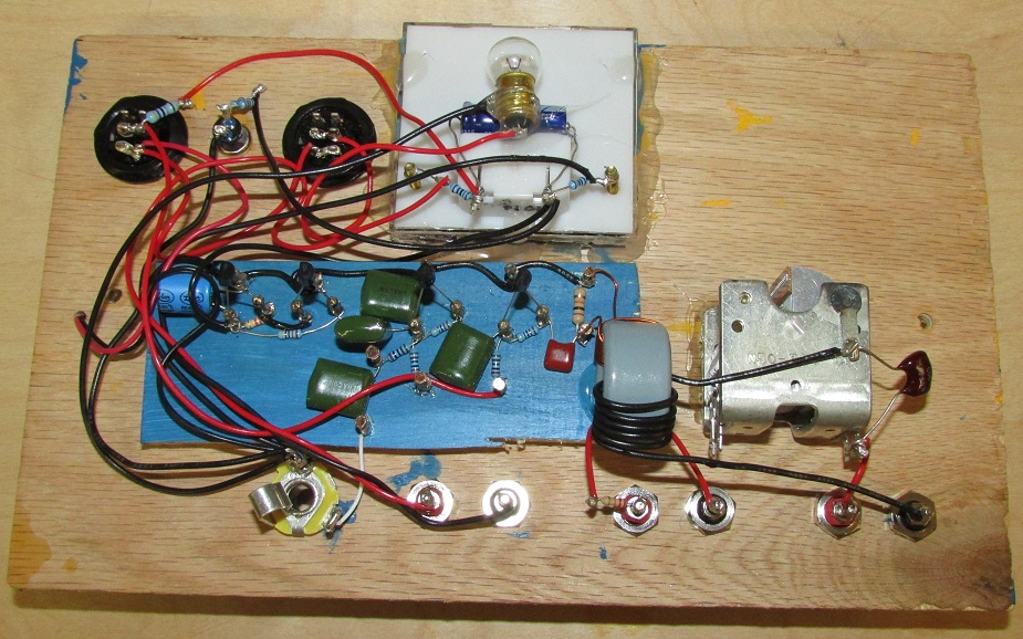
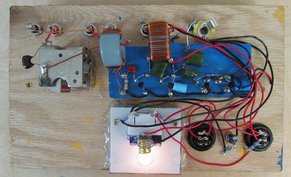
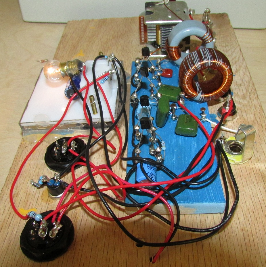
06-05-20-15, A small wooden board was used. Copper tacks were hammered into it.
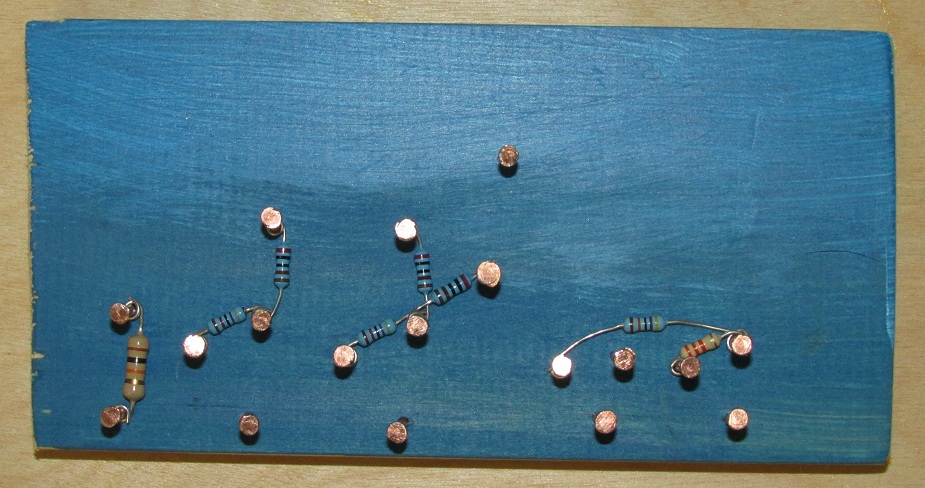
Place all the resistors first like shown. Do not solder anything yet. Soldering will be done later.
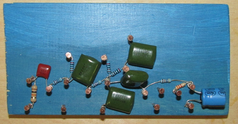
After placing the resistors, place the capacitors like shown.
After placing the capacitors, place all the jumper wires between the tacks like shown.
After placing the jumper wires, place the wire leads. make them about 12 inches long for now. You can cut them shorter later as needed when soldering.
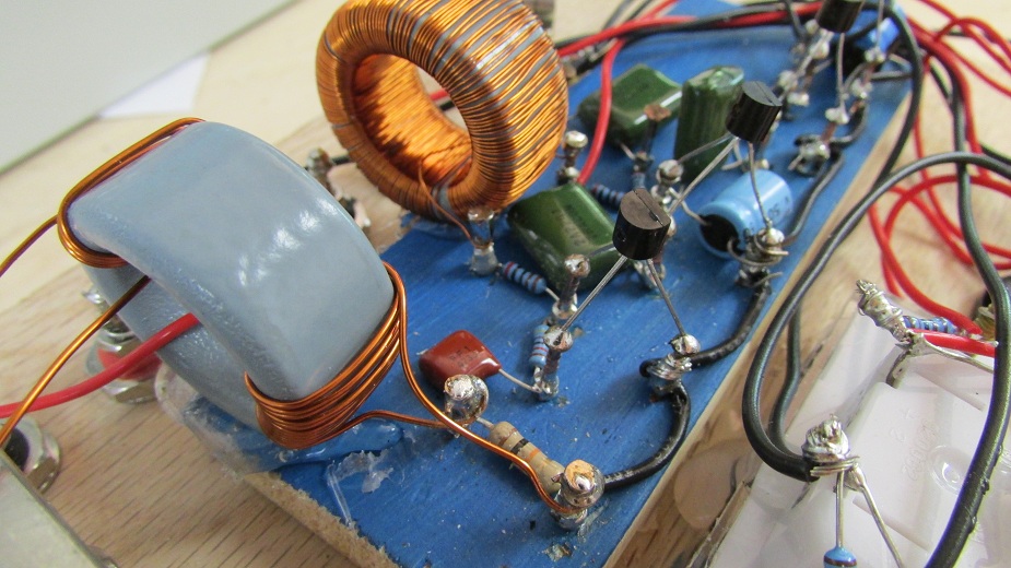
Wind the VLF transformer core with 12 turns of 22 gage magnet wire like shown. This is 12 turns that go thru the center of the core, like shown. Make sure to sand down the end leads with sand paper so you can easily solder this part.
NOTE: We added the RFC1 part later, it is not shown this or the next few photos, but see below in this page for placement of RFC1 and also C5 changed to 1 uF instead of the 0.22 uF shown in the photos.
Mount the VLF transformer core with the 12 turns of wire like shown in this photo. Use hot melt glue to glue it down to the wood board. You will add the additional 4 antenna turns and the 1 turn BFO input wire nearer to final soldering steps. See modifications section below on this page, the 6 turns of black wire shown in photo were changed to 4 turns of magnet wire in the updated design.
Mount the transistors. It is easier to put a drop of solder on one of the copper tacks, then hold the lead of the transistor to that tack and heat the tack until the solder flows. This first lead holds the transistor in place making it easy to solder the other two connections. Be careful to not over heat the transistors when soldering as this can damage them.
Another view of the mounted transistors. Make sure to get all of the E B C connections right else the unit will not work.
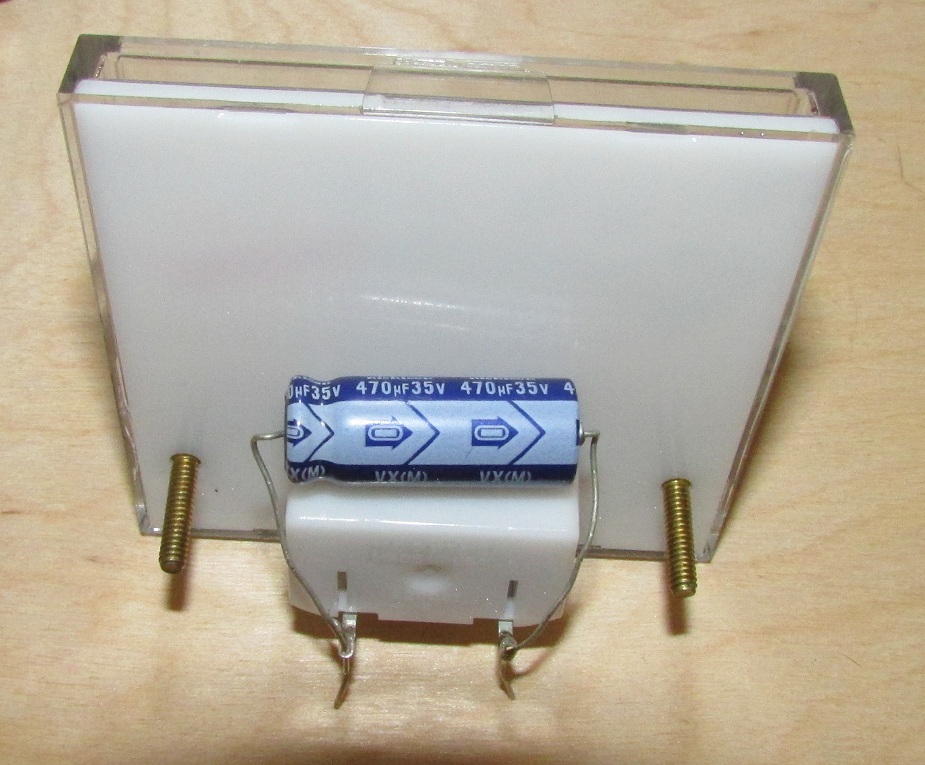
Mount the 470uF electrolytic capacitor on to the meter's leads. Make sure to connect (-) and (+) leads correctly.
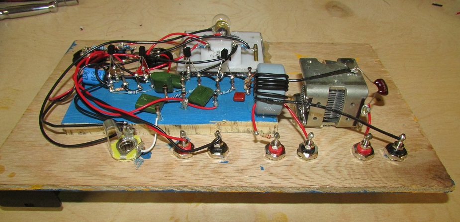
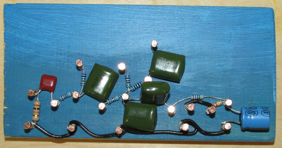
We made some modifications on 6-6-2015 which are very important to allow the receiver to work well across the full 10 KHz - 300 KHz range: We added RFC1 RF Choke and changed C5 to 1 uF. See the following photos:
6-6-2015: We changed out the 6 turns of black wire used for L1 coil to 4 turns of 22 gage magnet wire as indicated in the parts list above on this page. See photos below for details.
Revision 6-6-2015:
Revision 6-8-2015: Changed R11 and R2 to 100 K ohms, the higher value helps eleminate RFI pickup from computer data logger.
Revision 6-8-2015: Moved R12 position to that now shown in the circuit diagram above on this page. Output is no longer taken directly out of the meter. This gives a higher level of output for clearer recordings.
Revision 6-8-2015: Changed R9 from 50 ohms to 150 ohms, to prevent meter from slamming on strong signals. Meter now goes to maximum printed scale for the strongest signals. Calibration was done using rechargeable batteries installed, as we will be using those instead of standard alkaline batteries.
Revision 6-11-2015: See photos below on this page.
The receiver works great and is very sensitive.
(1). An audio output transformer to match headphones directly to the output without needing extra amplification.
(2). A 50 ohm antenna input to allow remotely locating the tuned antenna outdoors with a coaxial cable or twisted pair, and can have less noise.This will simply be an additional binding post on the front panel which connects to the tuning capacitor's case. This will allow connecting a cable directly to the existing L1 4-turn coil which gives a 50 ohm match down to 9 KHz.
To obtain a 50 ohm match with the SER22T antennas, connect a tuning capacitor directly across the antenna's terminals. Next wrap between 1 to 10 turns of wire around the center of the antenna's case to obtain the desired signal strength and selectivity needed. More turns gives less selectivity, less turns gives more selectivity. As you approach the 50 ohm match point signal strength will not be greatly increased by adding an extra turn. Adding more turns beyond this point will result in less selectivity.
NOTE: High selectivity can be heard in VLF receivers by how the channel makes a 'ringing' note when static is received when tuning off center of a station. Bandwidths can run less than 100 Hz with some antennas when at 50 ohm match.
NOTE: The receiver's built-in tuning capacitor will not operate when it is bypassed so the antenna will need to be tuned remotely.
NOTE: correct match is obtained when signal strength does not increase any when adding one more turn to the link wrapped on the antenna's case. Remove the extra one turn that did not give much extra signal strength. Over coupling may result in broad bandwidth (less selectivity) and more static noise. This broadening effect is good if you are using the receiver for lightning detection where broad bandwidth is desired.
From studying the diagrams and the photos you will notice that all inputs and outputs are electrically isolated, except for the audio output and the meter voltage output.
We will be winding an audio transformer on a separate 'Stormwise VLF-LF Transformer Core # 1' to provide RFI isolation and an 8 ohm match to some mono headphones to allow listening without needing an external audio amplifier-speaker.
Presently at date of 06-07-2015, WWVB 60 KHz can be heard by using a 16 ohm speaker at very low volume when placed up to the ear. An audio transformer will give a much better impedance match to the speaker or headphones producing louder sound than the 2000 ohm audio output impedance it now has. Do not change or omit R6 or C3 for this modification, else the signal strength meter will need to be recalibrated.
06-09-2015: Audio transformer designed and tested but not yet installed.
06-9-2015. Next step is to install the audio transformer and design the 50 ohm additional antenna input.
06-10-2015. The 50 ohm input will just be a binding post connection to the other side of L1, which will allow bypassing the tuning capacitor. L1 already at 4 turns gives a 50 ohm match across the full 10 KHz - 300 KHz range.
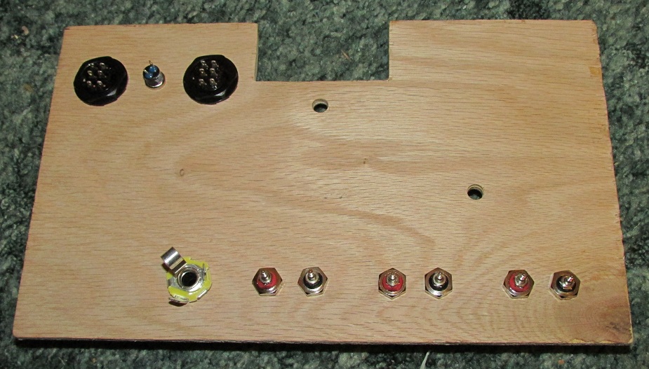
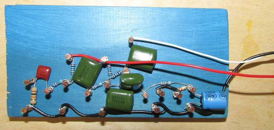
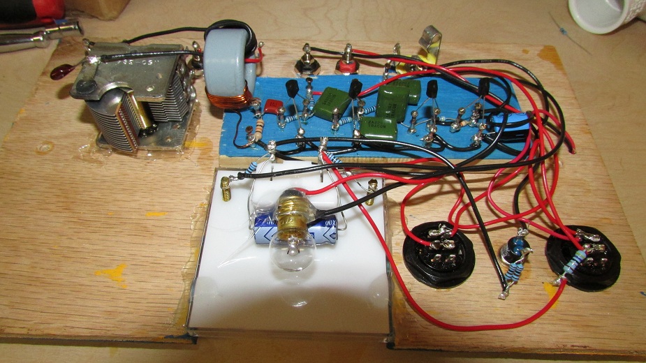
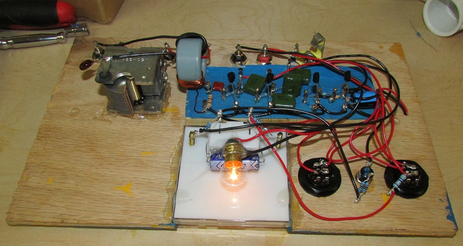
Revision 6-11-2015 Photos: added audio output transformer and 50 ohm antenna input binding post.
The audio output transformer's primary consists of 500 turns of 28 gage magnet wire wound on 'Stormwise VLF-LF Transformer Core # 1'. The primary's impedance is 2500 ohms at 300 Hz.
The secondary consists of 25 turns of 28 gage magnet wire wound on top of the primary winding. The secondary's impedance is 8 ohms at 300 Hz.
This audio transformer provides added RFI isolation and allows driving 8 ohm mono headphones at low volume directly from the receiver's output jack without needing extra amplification.
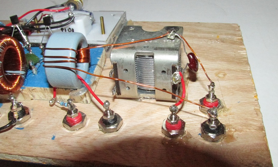
A wire was connected to the tuning capacitor and a new binding post to allow connection to a 50 ohm tuned antenna operating either series tuned or parallel tuned mode.
The 50 ohm input allows the SER22T antenna to be located at a greater distance outdoors and connected via a twisted pair cable. The antenna must be tuned remotely with its own separate capacitor when using this input, as the internal tuning capacitor is bypassed. Series tuned and parallel tuned antennas are supported, the SER22T antenna can be tuned in both ways.
Revisions 6-13-2015:
(1). Removed C7 470 uF from meter for faster meter response to quick transient signals such as lightning, clipped one lead of the capacitor.
06-13-2015: Receiver wiring diagram with all modifications and additions, except for C7 is still shown in the circuit.
Lightning Detection: You can turn the receiver into a lightning detector: Just put a 3 volt piezo buzzer across the meter circuit and tune the antenna to 60 KHz. Lightning static will cause the buzzer to make clicking noises for each flash. Signal from WWVB should not affect the buzzer and you don 't need the BFO input for this to work. The antenna is directional so you can turn it to completely null out WWVB if you so desire.
NOTE: if the buzzer is used in BFO Mode, the buzzer can be made to BEEP for each WWVB pulse when signal is strong enough, kind of an audible signal strength indication.
Revision 06-26-2015: Changed L1 to 2 turns instead of 4 turns, which gives higher Q and narrows the receive bandwidth, eleminates some noise.
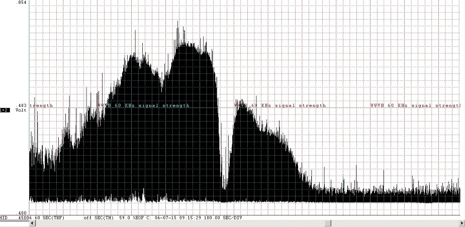
WWVB's signal strength is strong at night but when the sunlight first hits the ionosphere layer there is a sudden drop in signal strength. This effect can be observed at frequencies below 400 KHz.
In this recording the top of the graph is the WWVB signal level, the bottom of the graph is the noise floor reading, due to the fact that WWVB pulses ON and OFF, allowing both signal strength and the background static level to be seen on the chart.
The chart speed of this recording was 3 minutes (180 seconds) per division.
The receiver was tuned to 60 KHz and a BFO input of 59.6 KHz was input. BFO drive level was around 0.15 volt rms. This gave a VU meter reading of 100 percent or '0 dB' when WWVB was coming in very strong. There was some room left for signals to increase in level.
The antenna was indoors laying on the floor for this test. In the future the antenna will be mounted outdoors about 1 foot above ground over a concrete slab.
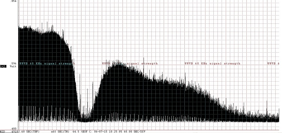
Magnified view of the above chart.
Each sunrise is different. Here are some examples.
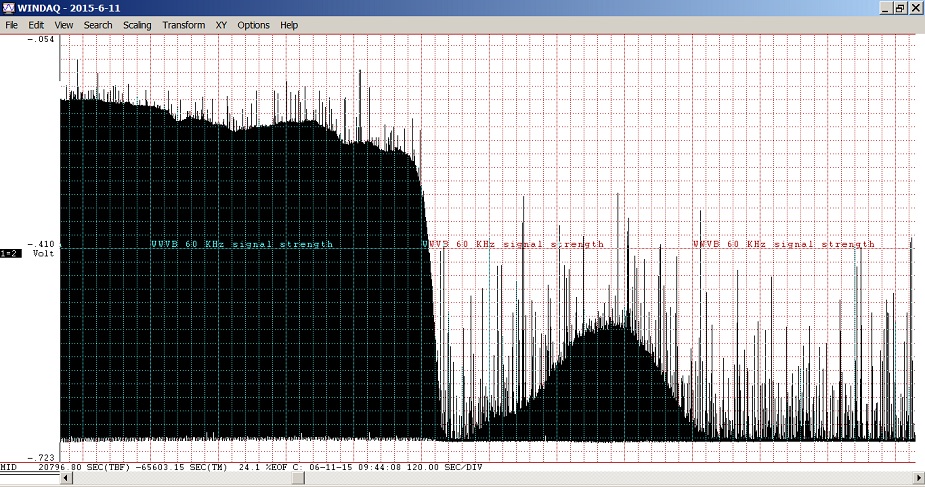
Morning of 6-11-2015.
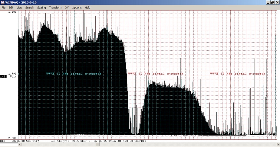
Morning of 6-16-2015.
Notice how there is a different time each morning at which the signal drop off starts. This is in relation to the slowly changing time of sunrise each morning.
ECLIPSE 2017
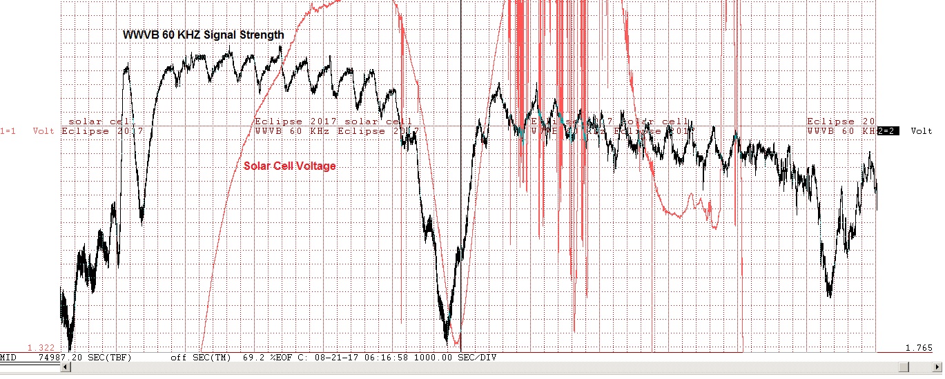
We monitored WWVB on 60 KHz and also placed a solar cell outdoors during the eclipse on August 21, 2017 and got these results here by using a computer and a data logger. This is the type of research that can be done with receivers in this frequency range. We were able to see the effect the eclipse had on the propagation of LF radio signals. The signal strength increased near the time of maximum coverage. Here we saw about 75 percent of the sun covered, it was a partial eclipse for us.
As the moon blocked the sunlight the voltage on the solarcell --decreased-- and the signal strength at 60 KHz --increased-- (We inverted the data so they would fit together in the chart above).
VLF and Longwave Receiver for High Impedance "C" Antennas.
Lightning Detector project 11.
ELF Extremely Low Frequency Receiver. project 12.
Longwave and VLF Receiver with Signal VU Meter.
VLF Receiver with Signal Strength Meter.
Wideband ULF - VLF FET Pre-amplifier.
07-08-2011. This direct input tuned receiver works with our Model "C" antennas above on this page, in the range of 10 KHz to 530 KHz.
07-16-2011. Uses our Lightning Detection Antenna part # D6T-3KC-BC.
07-19-2011. For use with any of our high impedance ELF antennas.
