|
|
|
|
|
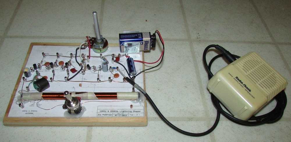
This lightning detector will detect distant lightning flashes before the storm arrives. The alarm sounds thru any audio amplifier as a series of crackling static pops.
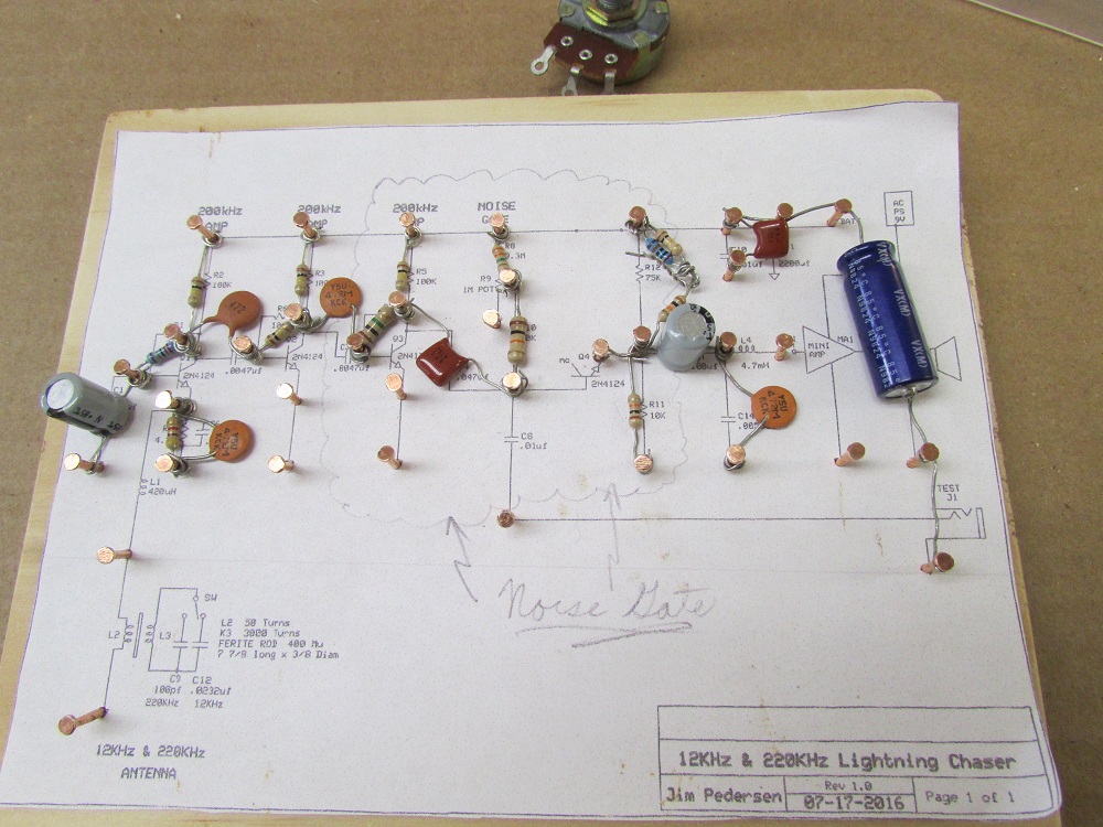
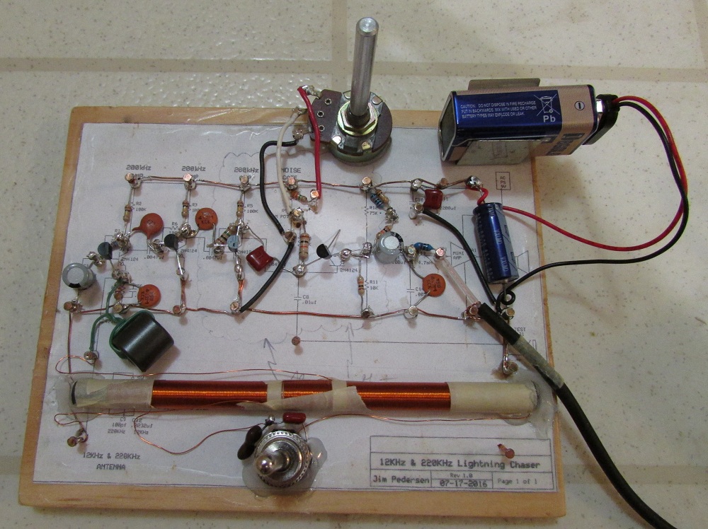
Jim Pedersen built this circuit on 07-17-2016 using our original Stormwise Lightning Detector plans and then improved the unit by adding an adjustable 'Noise Gate' squelch control that eleminates all background noise spikes and power hum so it can work in less than optimal reception conditions.
This directional lightning detector uses electro-magnetic field sensing at a very low frequency of 12 KHz for long range detection. Flipping a switch changes the frequency to 220 KHz for short range detection to allow determining if the lightning is coming nearer.
The 12 KHz VLF frequency detects cloud-to-ground lightning. Over 500 miles range is possible at maximum range setting. The 220 KHz channel detects both cloud-to-ground lightning and also in-cloud lightning flashes.
The output alarm is the sound of lightning static popping, which is amplified by any audio amplifier or portable guitar amplifier having a built in speaker.
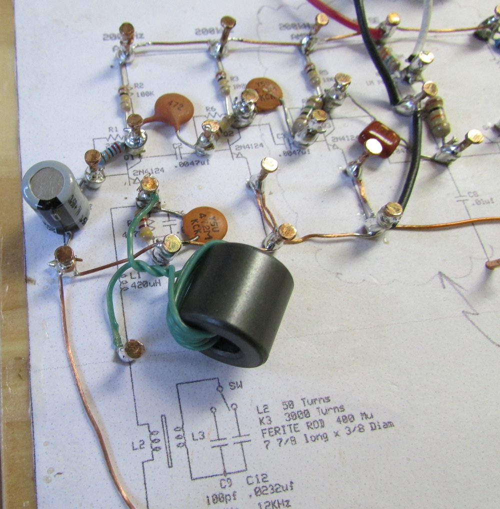
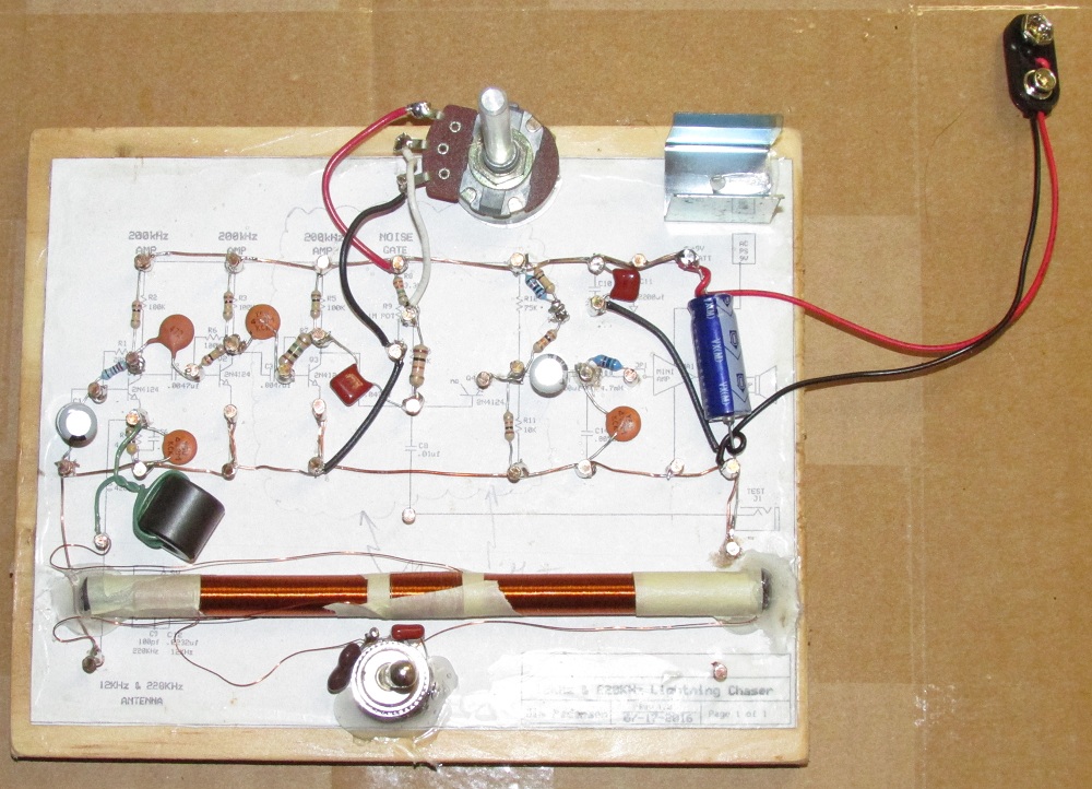
We built this project using our own style choice of assembly tecnique: Point to point wiring, using copper tacks hammered into a wooden board. You may opt to build it this way, or you may choose to use another method such as a printed circuit board or even an experimenter's breadboard.
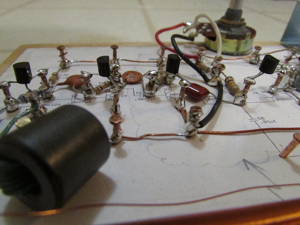
We find this point to point method works quite well. The transistors are soldered on top of copper tacks for easy replacement if ever needed.
Parts List:
| Part # | __Price |
|---|---|
| Transistors: | |
| Q1, Q2, Q3, Q4: NPN Transistors. 2N4124. | $ 0.95 each |
| Capacitors: | |
| C1: 47 uF electrolytic capacitor. | $ 0.95 |
| C2: 0.0047 uF capacitor. | $ 0.35 |
| C3: 0.0047 uF capacitor. | $ 0.35 |
| C4 = 0.047 uF capacitor. | $ 0.35 |
| C5 = 47 uF capacitor. | $ 0.95 |
| C6 = 0.0047 uF capacitor. | $ 0.35 |
| C8 = 0.01 uF capacitor. | $ 0.35 |
| C9 = 100 pF capacitor. | $ 0.35 |
| C10 = 1000 pF capacitor. | $ 0.35 |
| C11 = 470 uF capacitor. | $ 2.50 |
| C12 = 0.033 uF capacitor. | $ 0.35 |
| C14 = 0.0047 uF capacitor. | $ 0.35 |
| Resistors: | |
| R1 = 220 K | $ 0.35 |
| R2 = 100 K | $ 0.35 |
| R3 = 100 K | $ 0.35 |
| R4 = 4.7 K | $ 0.35 |
| R5 = 100 K | $ 0.35 |
| R6 = 100 K | $ 0.35 |
| R7 = 1 Meg | $ 0.40 |
| R8 = 3.3 Meg | $ 0.50 |
| R9 = 1 Meg control | $ 1.95 |
| R10 = 10 K | $ 0.35 |
| R11 = 10 K | $ 0.35 |
| R12 = 75 K | $ 0.50 |
| R13 = 47 K | $ 0.35 |
| Switch: | |
| SPDT switch. (may look differant than one shown) | $ 2.90 |
| RF chokes and cores: | |
| RF Choke core Stormwise part # CC-1 for L1 | $ 2.00 |
| L4 = 4.7 mH RF choke | $ 2.50 |
| Antenna Ferrite Rod: | |
| L3 = ferrite rod Stormwise Part # ROD-316-5625-M | $ 12.95 |
| Antenna Wire and Connecting Wire: | |
| # 30 magnet Wire for winding L1 and L3. | $ 2.00 |
| # 24 magnet Wire for connections. | $ 2.00 |
| # 22 wire insulated wire for misc connections. | $ 2.50 |
| 9-volt battery power snap | $ 1.25 |
| 9-volt battery holder clip | $ 1.50 |
Note: Some parts may look different than shown in the photos, depending on our parts sourcing and availability.
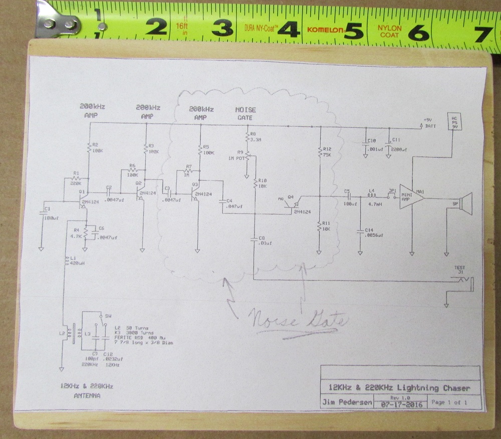
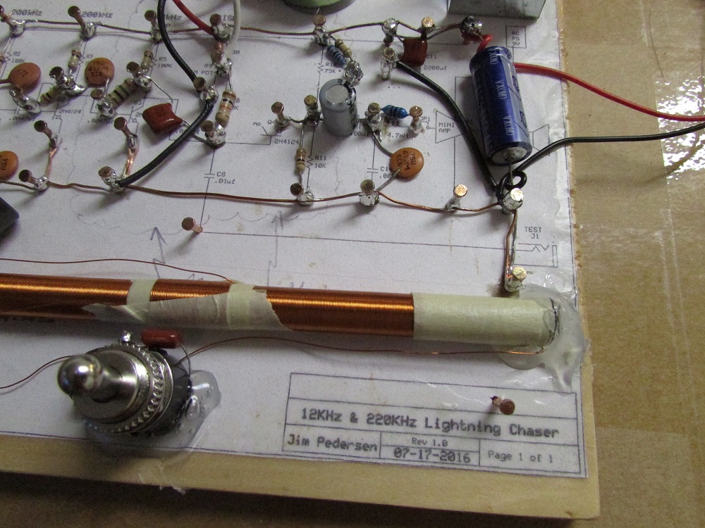
We printed out the circuit diagram on paper to fit as shown on a 6.75 inch x 5.5 inch wooden board.
The circuit diagram printout border measures 4 and 13/16 high by 6.5 wide when scaled down to correct size.
Obtain some copper-plated weatherstrip nails. 3/4 x 17 size.
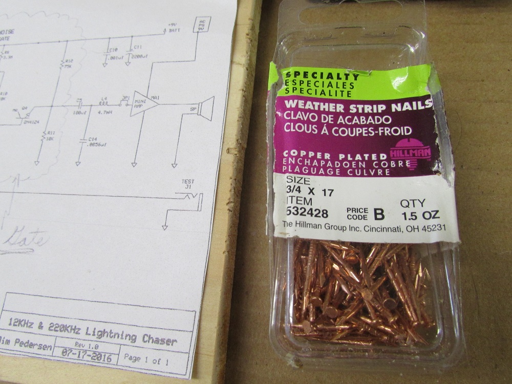
Using a hammer, nail the copper weatherstrip nails into the connection points as shown.
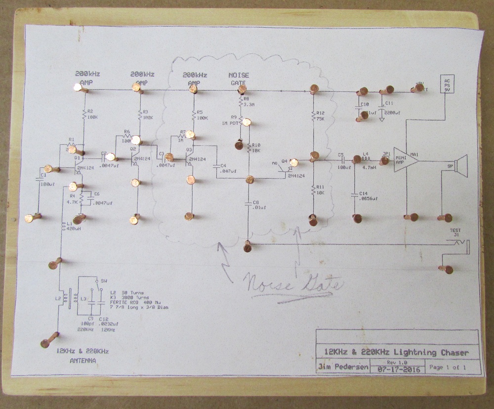
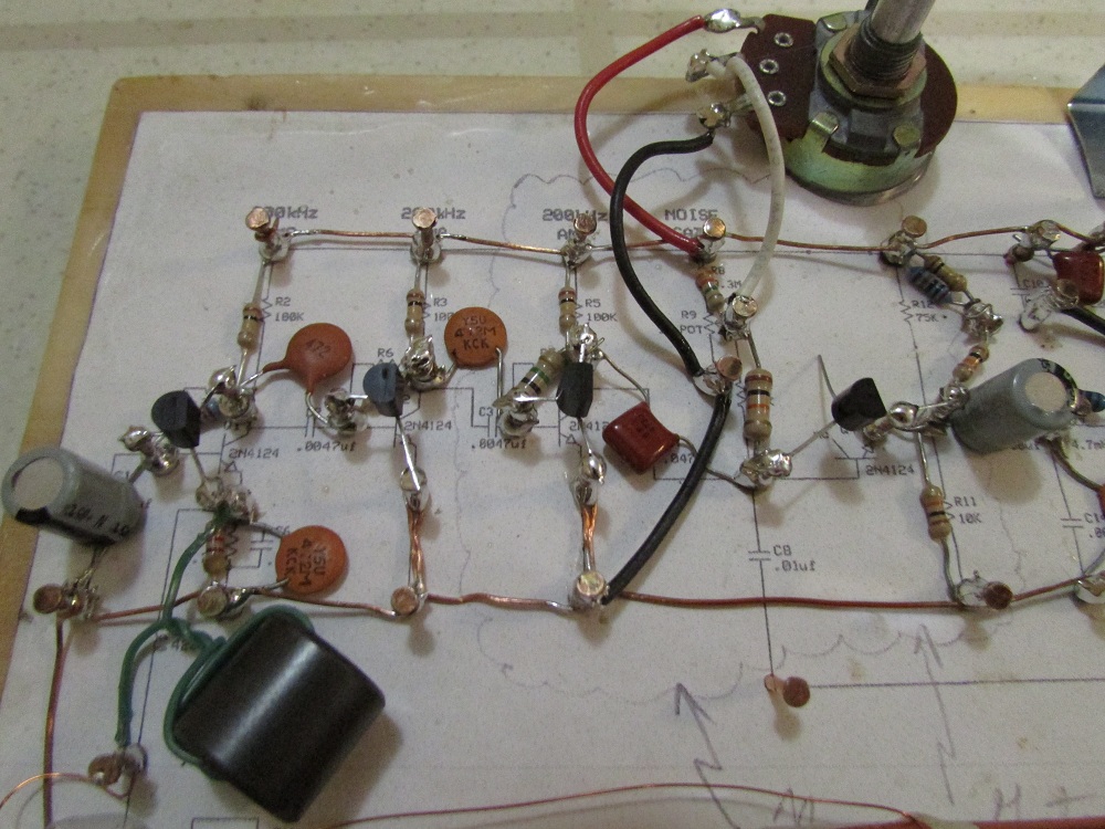
Install the capacitors and resistors first. Wrap the wires around the nails as shown. Make sure capacitor polarity is correct where applicable.
Install the negative buss line wire. Use 24 AWG copper wire, sand down the varnish insulation to expose the solderable copper wire. Wrap the wires around the nails as shown.
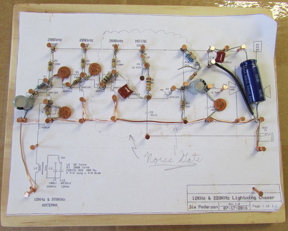
Install the Positive buss line wire. Use 24 AWG copper wire, sand down the varnish insulation to expose the solderable copper wire. Wrap the wires around the nails as shown.
Install the 1 Meg Control Resistor. Connect as shown with jumper wires to the nails as shown. See note below this photo. Hot melt glue the control to the wood board.
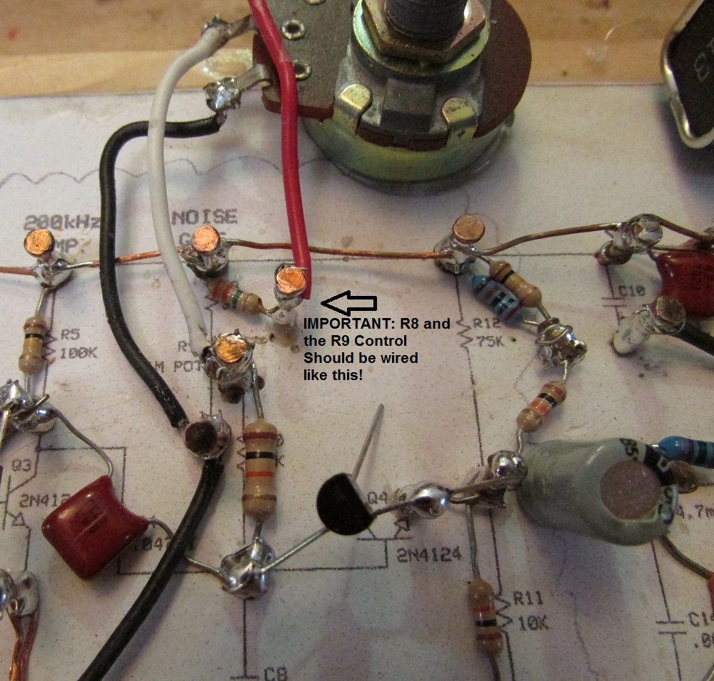
NOTE: Updated design: Place 1 more tack and move R8 connection to it as shown ABOVE.
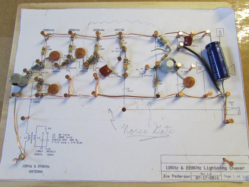
Wind 7 turns thru the center of the RF choke core. The inductance value will be 400 uH. Twist leads and connect to the nails as shown.
Verify and solder all connections made so far.
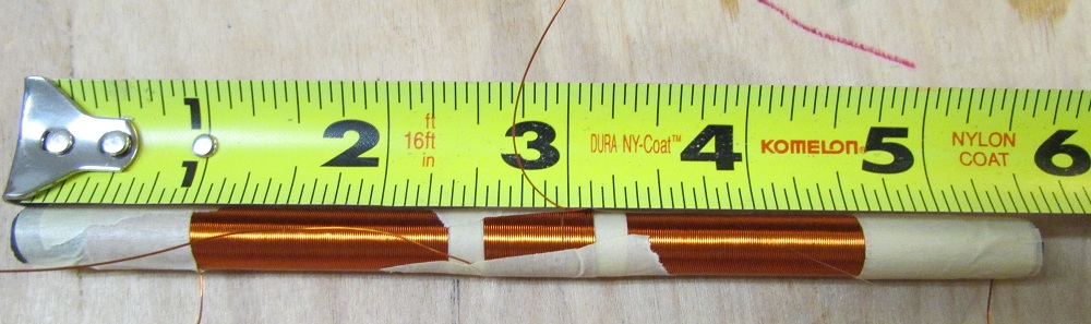
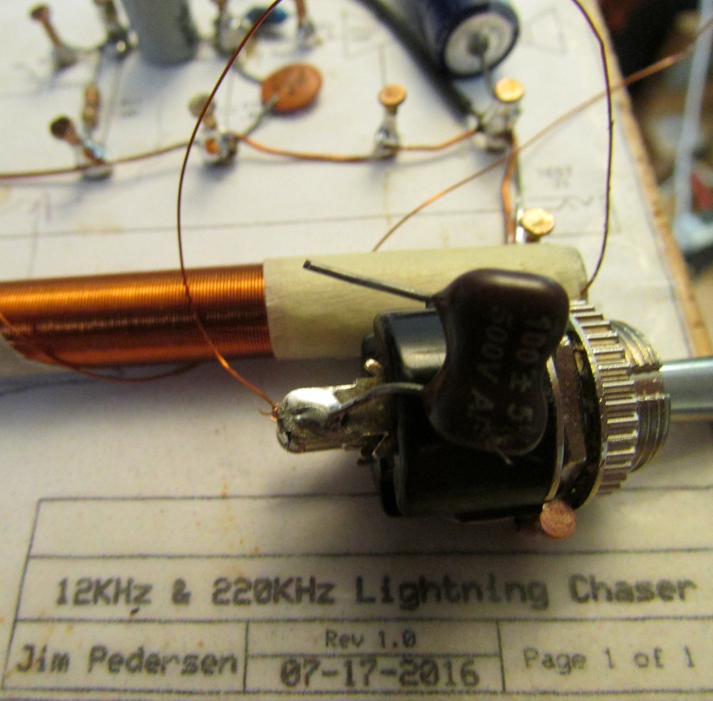
Wind 410 turns of # 30 AWG copper wire on the ferrite rod. Cut wire and leave 3 inches of wire for connection. Use sandpaper to gently remove the insulation. Do not apply too much pressure which will break the thin wire.
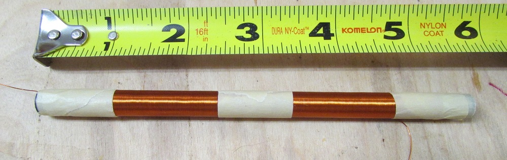
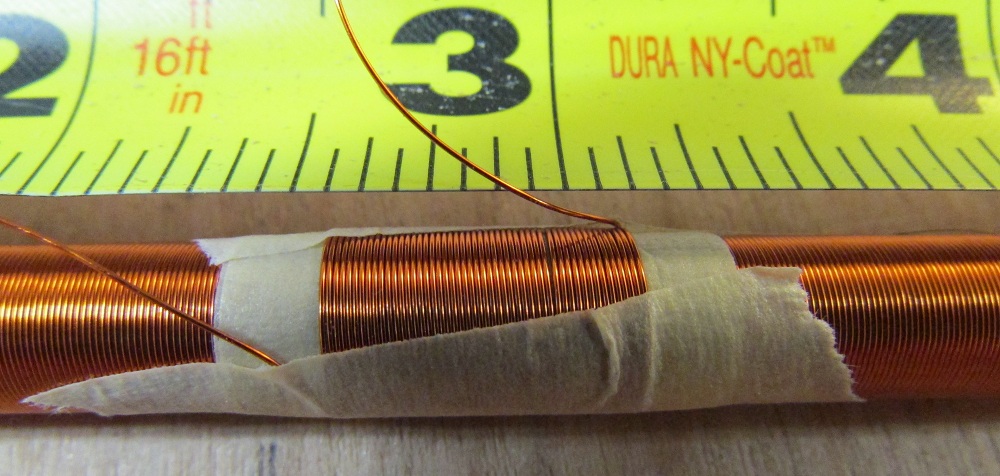
Place a piece of masking tape about 1 inch wide on the center of the 410 turns. Wind 50 turns of AWG # 30 on to this tape. Leave 4 inches of wire extra on each end for connection. Use sand paper to gently remove the insulation.
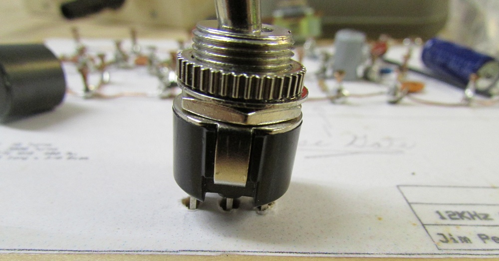
Drill 3 holes for the SPDT switch terminals to sit down into. Should not be too tight, as do not want to break the wires when pushed down into holes.
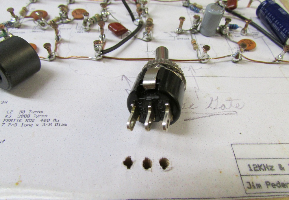
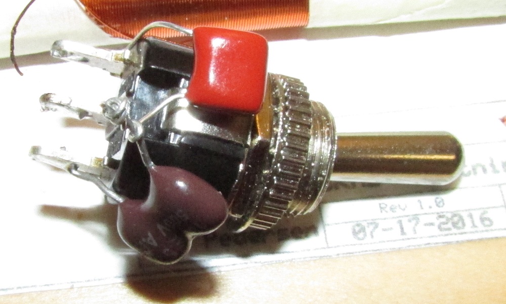
Solder the 100 pF capacitor to one side of the SPDT switch like shown.
Solder the 0.033 uF capacitor to the other side of the SPDT switch like shown and twist the ends together, and do not clip off, a wire will be connected to this a few steps later on.
Solder the right side wire from the 410 turns to the center pin of the SPDT switch like shown.
Solder the left side wire of the 410 turns to the twist point of the 100 pF and 0.033 uF capacitors like shown, and put the switch pins into the 3 drill holes like shown.
Solder the right side wire of the 50 turns to the 400 uH RF choke connection nail, as shown.
Solder the left side wire of the 50 turns to the bottom left nail ground bus connection as shown.

Hot melt glue the ferrite rod and the SPDT switch in place. Use as little glue as needed, don't over do it. Do not get glue on the wires.
Connect the 9-volt battery snap to the C11 capacitor connection nails. Wrap the batter leads once around the capacitors leads to help prevent wire breakage.
Place the 9-volt battery holder in the upper right corner of the wood board. Hotmelt glue down, and us a screw to hold.
Place the 2N4124 transistors lastly. The flat face of the transistor should face like shown. Make sure that the E, B, and C leads of the transistors go to the correct terminals. Solder on pin to one of the nails, then solder the other 2 transistor connections. Do not overheat the transistors while soldering.
Connect a 9-volt battery to the battery snap.
Connect the lightning detector to an audio amplifier or guitar amplifier's microphone type input. Input sensitivity should be rated at 1 mV at around 5000 ohms.
Move the detector away from any speakers (to prevent audio feedback squeals).
Set the SPDT switch so the detector is set for 12 KHz.
Set the Noise Gate control to the middle range.
Turn ON the amplifier and turn up the volume until the hissing and general hum and static noise is loud.
Adjust the Noise Gate control to the middle setting and you should hear noise and static reception.
Adjust the Noise Gate control SLOWLY to the right until the hum and hissing noise goes away, but the lightning static pops remain.
You now should hear ONLY the static popping from lightning, without any background hiss or hum noise. This is the correct function of the 'Noise Gate' circuit added by Jim Pedersen.
The detector can sense lightning over 500 miles away when in the 12 KHz mode.
You can adjust the Noise Gate control slightly more to the right to decrease the sensitivity more, to allow only closer storms to be detected.
If you want to receive at 220 KHz for shorter range, then flip the switch and re-adjust the Noise Gate control per the above steps.
Modifications:
Powering the unit: It is best to use rechargable battery power that is independant of the AC mains power, so that house electrical noise is not couipled to the unit thru the AC mains.
Adding a grounded sheet of foil (connect it to the [-] buss line ) under the board can improve performance: This will help to make sure the unit does not have any regenerative amplification or oscillations.