|
|
|
|
|
|
DC - 30 KHz
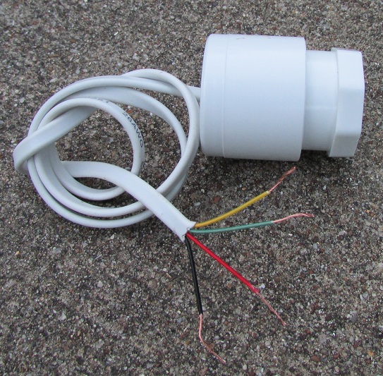
This weather-proof encapsuled instrumentation amplifier has high gain, high impedance, and amplifies DC to 30 KHz.
Designed to work with our ELF - VLF antennas, and it also amplifies signals from piezo elements, wire antennas, etc.
Operates on 9 to 18 volts DC. 12 volts recommended. Draws about 20 mA.
Easy 4 wire connection: Yellow = Input , Green = Output, Red = (+), Black = (-). Single power supply operation.
It is input protected and overload protected so that wiring mistakes will not damage it, even when powered at 18 volts.
Input impedance: 10M ohms. Output Impedance: 2K ohms.
Minimum support parts required: Input capacitor of 0.1 uF to 100 uF (depending on minimum receive frequency desired), battery, on/off switch, momentary switch, resistor.
Part # ELA-1 $ 35.00 + $ 8.00 s/h.
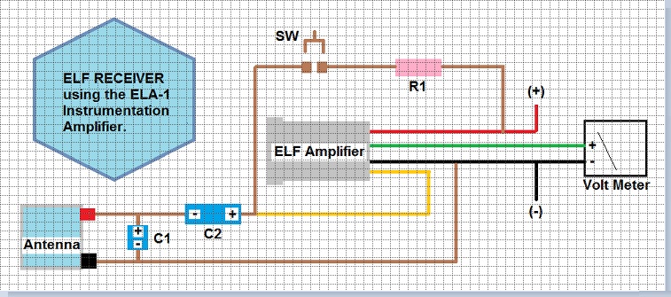
Support parts:
R1 = 10 K-ohm resistor.
C1 = Capacitor to tune your ELF - VLF antenna to desired frequency range.
C2 = 0.1 uF to 100 uF 35 volt capacitor.
SW = Momentary reset switch.
Instructions: When power is applied ( 12 volts DC ) press SW switch until volt meter reads 4 volts DC. Release switch. C2 is now 95% charged (assumes there is a DC path thru antenna or connected sensor). Amplifier will begin receiving ELF when capacitor settles to full charge. This may take a minute if the capacitor is greater than 100 uF. If you change sensors or antennas, the reset switch may need to be pressed again to reset the capacitor's charge. Capacitor remains charged while power is ON. If output voltage keeps dropping below 3 volts when powered at 12 volts, this indicates a leaky C2 capacitor. Use a type having extremely low leakage, with a volt rating of 35 volts or higher. If C2 is leaky, the output voltage level can be adjusted to compensate if needed by adding a high value ( 20 meg ohms to 50 meg ohms ) resistor across the red and yellow wire.
You can view ELF waves on any data logging DC volt meter, or PC data logger.
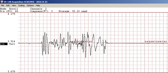
Chart shows the DC level of 3.914 volt when no input signal, and to the right shows how the voltage level changes in response to the ELF waves. In this case a small magnet being moved 5 feet away from the antenna.
Data chart using the DI-148 data logger from www.dataq.com. Up to 60 samples per second to allow 30 Hz waveforms to be viewed.
A single transistor can magnify the DC output by about 10 X to allow you to easily see weaker signals.
This works well with seismographs to boost the weak or very distant quakes.
IMPORTANT NOTE: When using the transistor booster: Nearby earthquakes 100 miles away of 4.5 magnitude or greater can drive the unit off scale, making the recording totally useless, or at the minimum bad-looking. It is recommended that a 2 channel recorder be used, and one channel records the transistor's 10 x boosted output, and the other channel records the unboosted output directly from the unit's green wire. This will prevent missing any events that would otherwise drive the recorder off-scale.
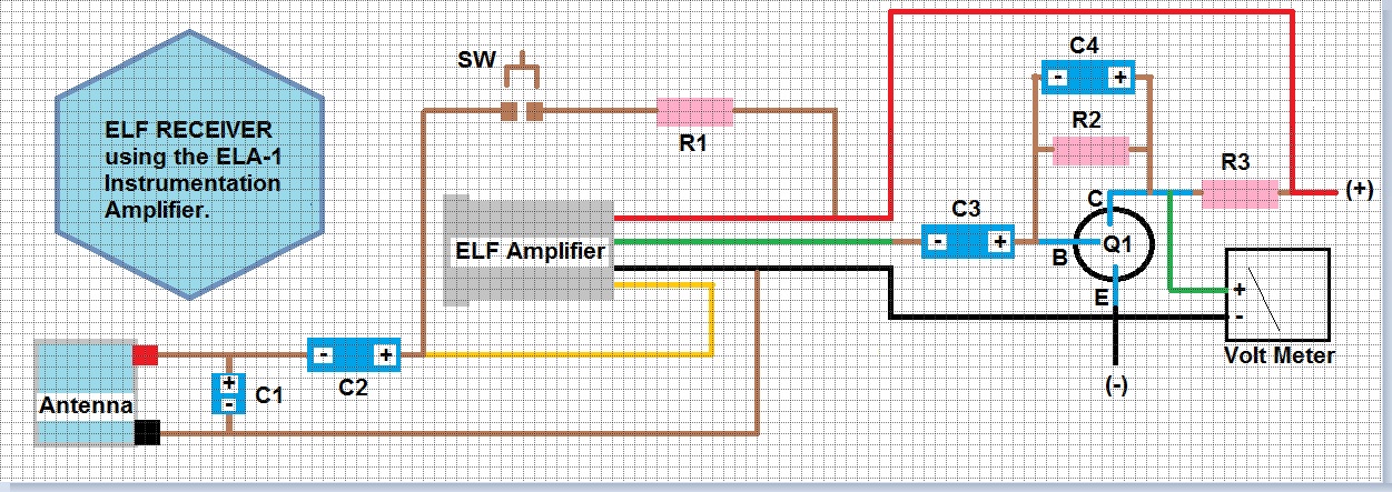
Support parts:
Q1= 2N3904 NPN transistor.
R1 = 10 K-ohm resistor.
R2 = 1 Meg-ohm resistor.
R3 = 4700 ohm resistor.
C1 = Capacitor to tune your ELF antenna to desired frequency range.
C2 = 0.1 uF to 100 uF 35 volt capacitor.
C3 = 47 uF capacitor. SW = Momentary reset switch.
NOTE: If you just want to receive from 0.5 Hz and up, then use a smaller value for C3 such as an 47 uF. C4 = 1 uF. (C4 limits high frequency response).
NOTE: Fine tuning the output voltage level: If needed: Adjust the value of R2 (in the range of 470 K - 1 Meg ) so that the volt meter reads 6 volts when no signal is input after all components have charged up and are stable.
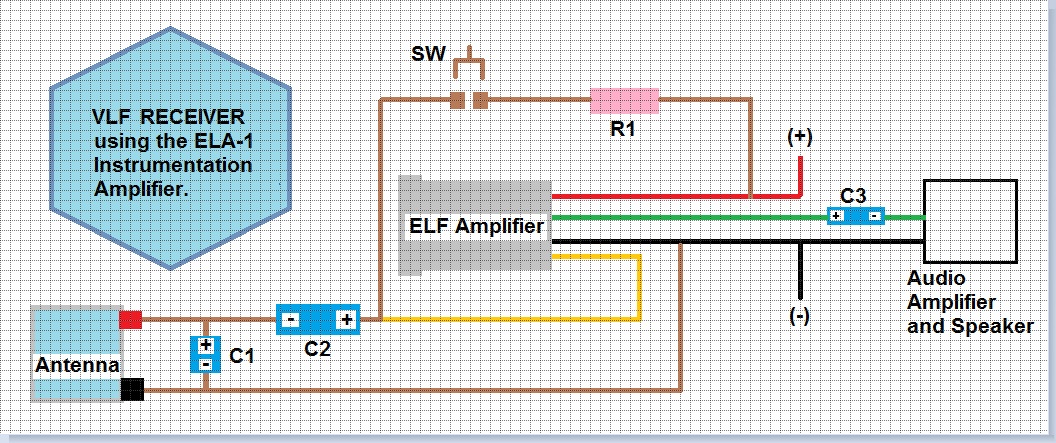
Support parts:
R1 = 10 K-ohm resistor.
C1 = Capacitor to tune your ELF - VLF antenna to desired frequency range.
C2 = 1 uF 35 volt capacitor.
C3 = 4.7 uF.
SW = Momentary reset switch.
Connect a portable battery powered audio amplifier or tape recorder to the output to hear the natural VLF radio sounds the earth makes.